Thermal Management Systems
This project involved designing, testing, and fabricating thermal components and systems to improve the heat dissipation of printed circuit boards (PCBs), digital micromirror devices (DMDs), and light-emitting diodes (LEDs). I began by selecting an off-the-shelf (OTS) heat sink to manage the thermal dissipation of an LED in a projector.
It soon became evident that the OTS heat sink alone could not achieve the required cooling performance. To address this issue, I implemented a solution to incorporate forced convection by utilizing a duct and a blower to enhance airflow through the heat sink's fins. I then measured the heat dissipation to determine if the necessary heat dissipation had been achieved.
Image 1: Right LED heat sink mounted to the projector.
The initial OTS heat sink did not meet the required heat dissipation capabilities. To improve efficiency, I selected an alternative OTS heat sink featuring hexagonal fins rather than flat fins. This design enhancement allowed for omnidirectional airflow, significantly increasing the heat sink's effectiveness.
Image 2: OTS heat sink with hex fins.
I then designed a custom heat sink that could be directly screwed into the LED, providing a stronger and more secure connection compared to the adhesive method used by the OTS heat sinks. This design also facilitated the use of a thermal gap pad, enhancing the thermal interface between the heat sink and the copper for improved heat dissipation.
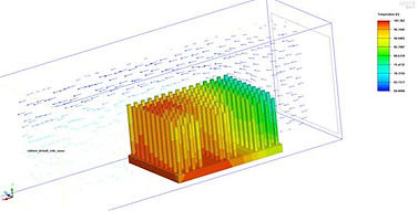
Images 3 and 4: Heat sink design and thermal simulation of final design.
I also designed a heat sink for a digital micromirror device (DMD). This design required additional hardware, including a washer and spring to ensure that the correct amount of force was applied to the mirror without causing damage.
Images 5-7: Design details of the DMD heat sink and associated hardware.
I then designed a preliminary model of blower ducts to position the blower correctly, ensuring optimal orientation to enhance airflow. This setup increased forced convection to 200 linear feet per minute (LFM) over the OTS heat sinks.
Images 8-10: CAD drawings of the left and right side of the blower air
ducts/ blower mount and real-life photos of them 3D printed on projectors.
The next step of the project involved designing the initial model of box fan ducts and selecting an off-the-shelf (OTS) box fan to generate more airflow over a larger area compared to the blowers.
Images 11-14: Box fan ducts depicting their use with the box fan.
Images 15-17: Final model of box fan ducts with assembly blower
depicting their use with the final screw on heat sinks.
The below flowchart is the design progression of the heat dissipation system for the projector LEDs.


